The robot has to know its own geometry before it can understand anything else. Ati Robotics explains how it calibrates cameras, LiDAR and steering on its AMRs, validates every estimate, and why calibration belongs in the safety conversation.
Key takeaways
- Calibration errors do not stay local. A wrong sensor pose or steering offset propagates through localization, sensor fusion, perception and control before it ever shows up as a visible behaviour problem.
- A flat floor constrains a LiDAR's roll, pitch and height but tells you almost nothing about yaw. Yaw needs a second known geometry. On Ati pallet movers, that is the prongs.
- Steering offset is only observable if the vehicle turns both ways. A figure-eight trajectory makes it estimable; straight-line driving does not.
- A good calibration pipeline should refuse to calibrate when data is insufficient, too similar, poorly fit or physically unreasonable. A bad calibration is worse than no new calibration.
- Offline calibration establishes trust. Online calibration checks whether that trust still holds.
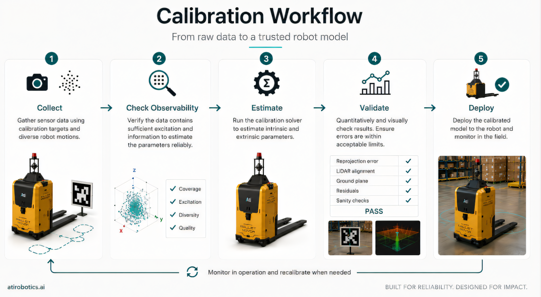 Figure: Our calibration workflow - Collect → Check observability → Estimate → Validate → Deploy
Camera Intrinsic Calibration: Focal Length, Optical Centre and Distortion
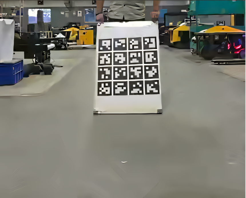
Camera intrinsics are probably the most familiar form of calibration to most engineers. We're estimating things like focal length, optical centre and lens distortion parameters, using a pipeline built on ArUco markers to get known correspondences between points on a calibration target and the points our cameras actually detect in the image.
 |
 |
|---|---|
 |
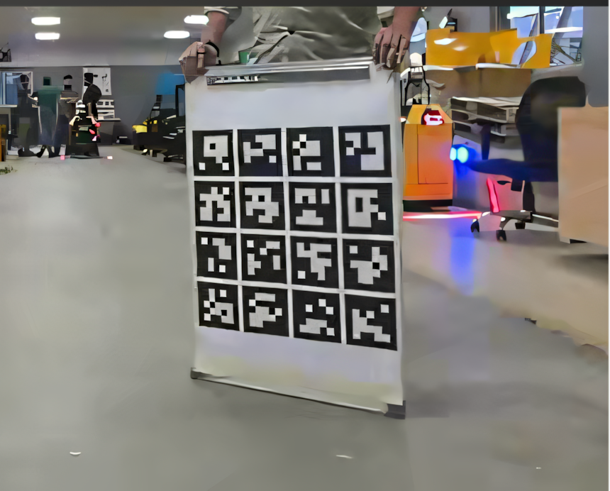 |
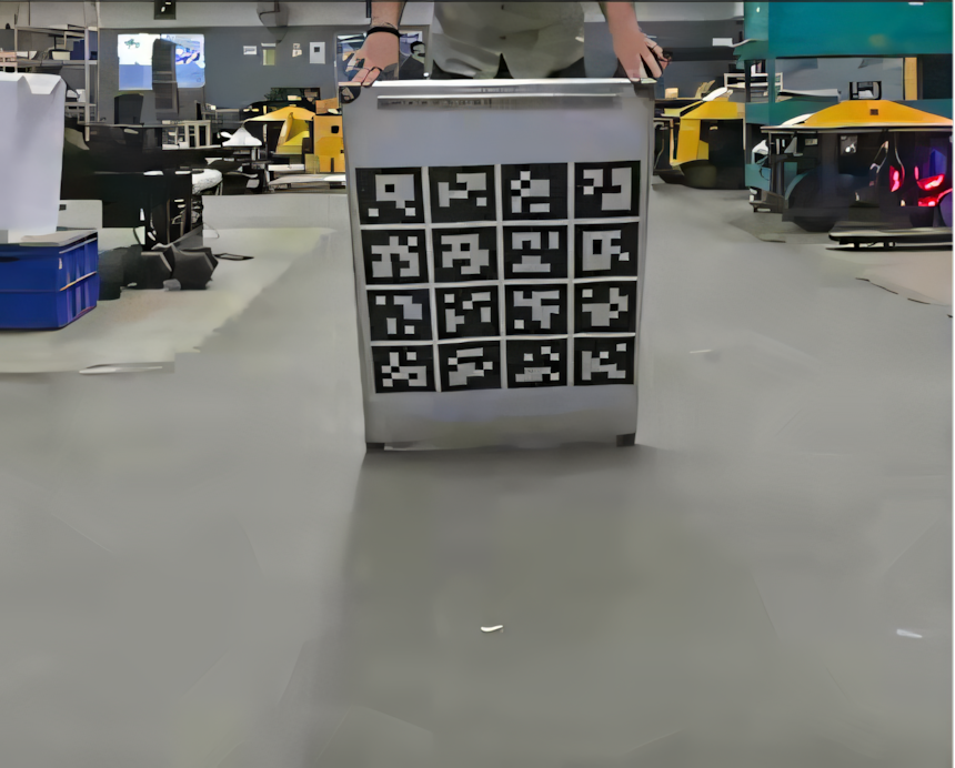
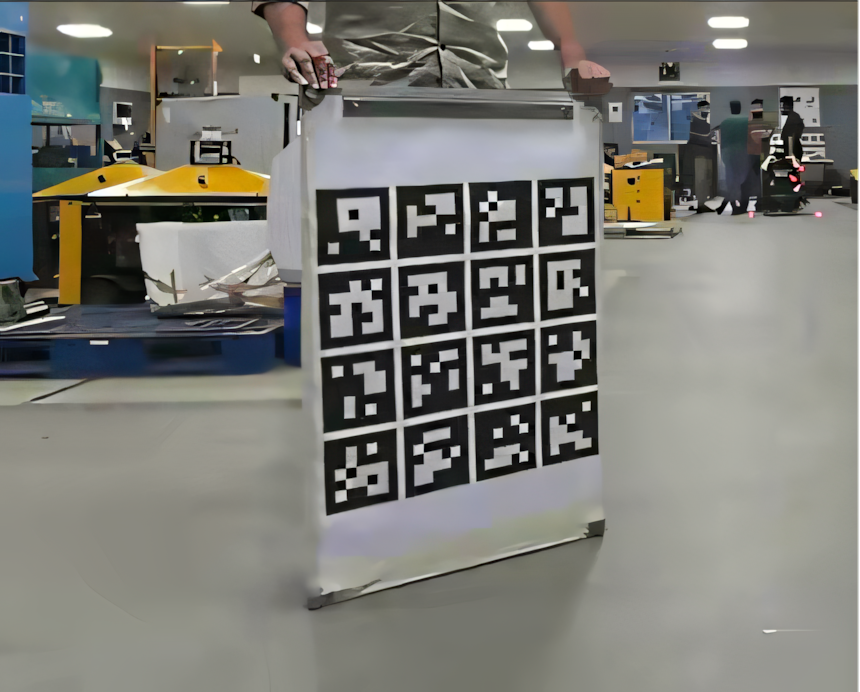
Figure: We collect camera images with the calibration target at different orientations and distances to ensure that the calibration target has sufficient useful information to estimate reliable and unique calibration parameters. Note that this is done both for intrinsic and extrinsic calibration.
But collecting a large number of images isn't the goal. The images need to contain useful information. Twenty images of the target from almost the same pose don't teach the model much more than one image would; what actually helps is variation: different orientations, different distances. So our calibration process checks for that variation before it trusts the data.
Once calibration is complete, we look at the reprojection error to see how closely the calibrated camera model explains what we actually observed. The philosophy behind all of it is simple: do we have enough useful data, does the estimate make sense, and can we verify it?
Extrinsic Calibration: Where the Sensors Actually Sit
The next problem is extrinsic calibration: figuring out exactly where each sensor sits and how it's oriented on the vehicle. A sensor might be designed to sit at a particular position, but the real installation is never mathematically perfect. Mounting tolerances, manufacturing tolerances and small mechanical shifts over time all add up, and even a small orientation error becomes significant once you're projecting measurements several metres away from the robot.
One thing we lean on heavily here is geometry that already exists around the robot, and the ground is the clearest example. On a reasonably flat surface, the ground plane gives us a strong reference for the LiDAR's roll, pitch and height. We identify ground points from the point cloud, fit a plane to them, and then check that the plane is actually believable: enough points support it, the estimated height is sensible, the orientation isn't unreasonable. Only after those checks pass do we use it for calibration.
That check matters more than it sounds. A solver will almost always hand you an answer. The harder problem is deciding whether that answer deserves to be trusted.
Why Ground-Plane Calibration Can't Estimate Yaw
A ground plane tells us a lot about roll, pitch and height, but almost nothing about yaw. Rotate a sensor around the vertical axis and a flat floor barely looks any different. It's an observability problem, not a math problem.
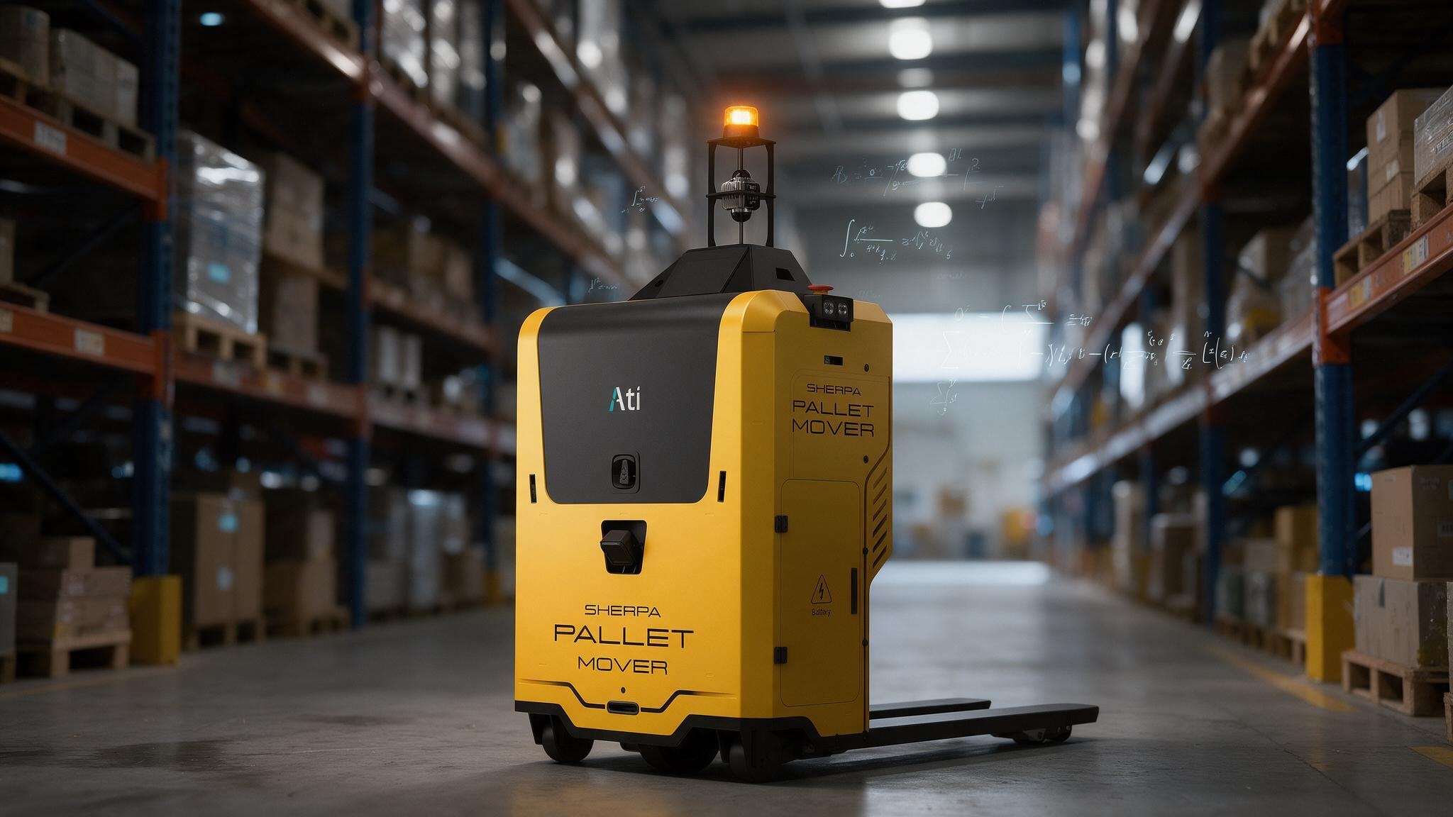
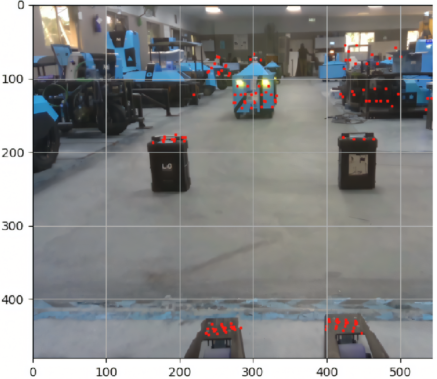 Figure: We use the prongs of our pallet-mover to calibrate the yaw between camera and lidar.
So instead of forcing one measurement to answer every question, we bring in another known piece of geometry from the vehicle itself. On some of our platforms, that means using the prongs mounted on the vehicle: their direction relative to the robot body is known, and by detecting that geometry in the LiDAR data, we can estimate the yaw correction we actually need.
This is a pattern that shows up constantly in calibration work. Different measurements tell you about different parameters, and good calibration isn't only about running the optimizer well. It's about understanding which parts of the system are actually observable from the data you're collecting in the first place.
LiDAR-Camera Extrinsic Calibration with a Planar Target
The same idea applies when we calibrate two sensors relative to each other. A camera and a LiDAR see the world in fundamentally different ways: the camera works in image coordinates, the LiDAR gives us direct geometric measurements. If we want to use both together, they need to agree on where things actually exist in the physical world.
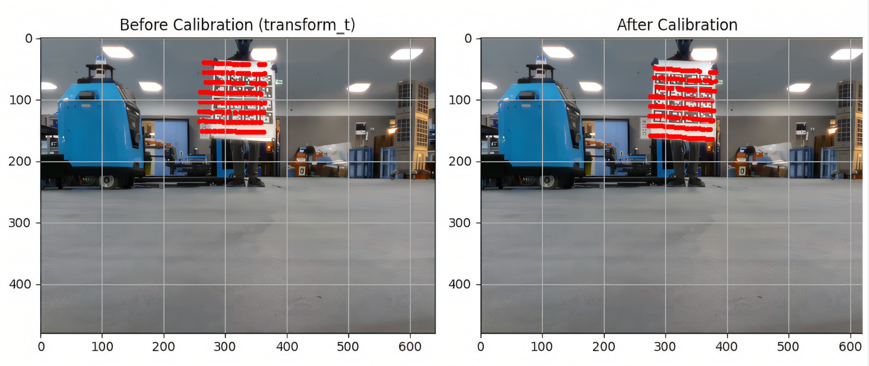 Figure: We use co-detection of calibration target in camera and lidar to estimate the unknown extrinsics. The left image shows how the projection of lidar points look like on calibration target with CAD estimates and the right image shows tighter projection after the target based camera lidar calibration process is complete.
For LiDAR-camera calibration, we rely on geometric observations that are visible to both sensors at once, and a planar calibration target works well for this. The camera tells us where the plane sits relative to the camera; the LiDAR gives us points on that same physical plane. Calibration then adjusts the relative LiDAR-camera transform until the two sets of observations line up consistently, and just like with camera calibration, we do this across multiple observations rather than trusting a single pose. Different orientations of the target give the process far better information about the real sensor transform.
Steering Offset Calibration Using the Robot's Own Motion
Calibration isn't limited to sensors. The vehicle itself carries parameters that shape how accurately we can model its motion, and steering bias is a good example. Say the steering system reports zero when the wheel is actually turned slightly. That gap can be too small to notice at first, but over distance, the motion the model predicts and the motion the vehicle actually makes start to pull apart, and that matters for localization, path tracking and motion control.
Our steering calibration compares what the vehicle model predicts against what the LiDAR observes the vehicle actually doing. From that difference, the estimator can work out whether there's a consistent offset in the steering measurement causing it. What I like about this approach is that the robot is, in effect, using its own motion to calibrate itself.
Read the research
The steering-offset and LiDAR extrinsic estimator described here is published in full: *Online Joint Calibration of Steering Offset and Planar LiDAR Extrinsics for Wheeled Mobile Robots *S. Mishra, A. Dhar, S. Majumdar, N. Arulselvan. arXiv:2608.26789, August 2026. https://arxiv.org/abs/2608.26789
Why We Drive Figure-Eights: Designing the Calibration Trajectory
The path the vehicle drives during calibration matters just as much as the estimator crunching the numbers. Drive only in a straight line, and some parameters simply can't be estimated. Turn only in one direction, and certain effects become hard to tell apart. So for steering calibration, we deliberately want the vehicle to experience a mix of motion: straight sections, left turns, right turns, all of it useful.
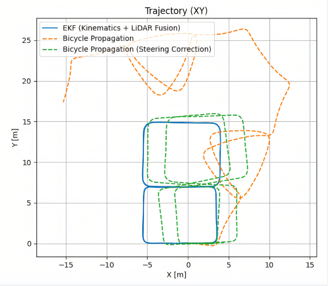 Figure: We do figure 8 runs to ensure parameter observability. Here we show the comparison of results between the EKF estimator that estimates the steering offset and accounts for it (blue), the uncompensated kinematic only motion propagation (orange), and finally the compensated kinematic only motion propagation (green) - clearly the kinematic model becomes more reliable post steering offset compensation.
A figure-eight trajectory works particularly well here, because it naturally produces positive and negative steering along with changes in both translation and rotation. The objective was never to collect a huge amount of data. It's to collect the right data, and that might be one of the most important lessons calibration teaches: more data doesn't automatically mean better calibration. More informative data does.
Fail-Safe Calibration: When the Pipeline Should Refuse to Calibrate
This sounds strange, but it matters: a good calibration system should sometimes refuse to calibrate. We'd rather find out now than ship a bad number when:
- There aren't enough observations
- The observations are too similar to each other
- The fitted geometry looks poor
- The estimated correction is physically unreasonable
A pipeline that always returns an answer isn't necessarily a good pipeline. In autonomous systems especially, a bad calibration can be worse than no new calibration at all, because the rest of the stack will simply assume the result is valid and build on top of it. So we wrap checks around the whole estimation process:
- Is there enough data?
- Is the data informative enough?
- Does the geometric fit look reasonable?
- Is the correction within an expected range?
- Does the result actually improve the measurements we care about?
Only once all of that clears does the calibration get to be useful.
Validation After Convergence
One thing we try hard to avoid is treating solver convergence as proof that the problem is solved. After calibration finishes, we still have to validate the result. For a LiDAR, that means checking whether the ground now appears level and known vehicle geometry lines up correctly. For a camera, it means looking at reprojection quality. For LiDAR-camera calibration, it means checking that observations from both sensors agree consistently. For steering calibration, one simple test is driving the vehicle straight after applying the correction and confirming the remaining estimated bias is close to zero.
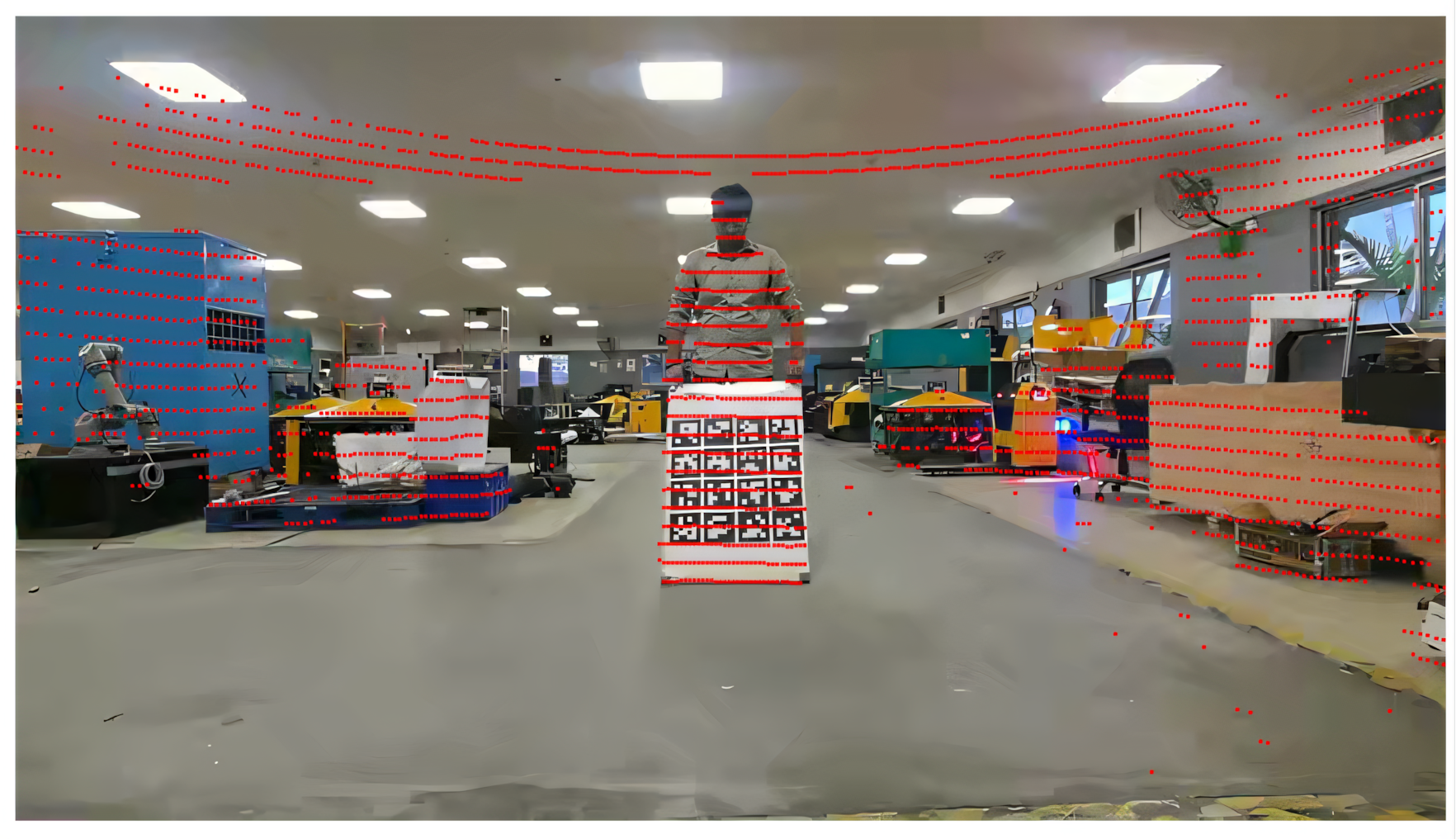 Figure: Representative verification result showing the LiDAR points projected onto the RGB image using the estimated lidar camera calibration. The projected points align well with the visible scene structure, indicating an accurate camera intrinsic and LiDAR–camera extrinsic calibration.
None of these checks are complicated. But they're what gives us confidence that the numbers coming out of the calibration process correspond to something real happening on the vehicle, not just a number the solver was happy with.
Calibration in the Field: Tooling for Commissioning Teams
Once calibration moves from development into deployment, it stops being purely a software problem. Software engineers build the algorithms and the tooling around them, but they're rarely the ones performing every calibration in the field. That job usually falls to validation engineers, commissioning teams or field operators, and it changes how the whole problem needs to be approached.
A calibration tool can be technically excellent and still be hard to use. If someone needs to understand ROS topics, manually inspect point clouds, edit configuration files or remember a long sequence of commands just to calibrate a vehicle correctly, we've pushed too much complexity onto the operator. A large part of productionizing calibration is really about UX:
- Can the operator clearly understand what needs to be done?
- Does the tool tell them when it has collected enough data?
- Can it explain why a calibration failed instead of just throwing an error?
- Can we cut down the manual measurements and inputs?
- Can the whole procedure fit into a simple SOP that someone can follow without understanding the estimator underneath it?
There are practical constraints too. A procedure that requires repositioning a heavy robot repeatedly, placing targets with a lot of precision, or spending a long time collecting data might work fine in development, but it gets painful fast once you're commissioning or servicing many AMRs. Calibration has to be designed for accuracy, but also for repeatability and ease of execution. Ideally, the operator performs a small number of simple actions, and the software takes responsibility for deciding whether what it collected is actually good enough.
This is where collaboration between software, validation and field teams matters most. The people actually using the tools surface problems that never show up while you're developing the algorithm. A confusing instruction, an awkward calibration trajectory, or a failure mode with no useful error message can matter just as much in production as an improvement to the optimizer itself. Good calibration software has two users: the estimation algorithm, and the person standing next to the robot trying to get the job done. Both need to be designed for.
Online vs. Offline Calibration for Production AMRs
A natural question is whether dedicated calibration procedures are even necessary. Why not continuously estimate calibration parameters while the robot operates? Online calibration, or self-calibration, has been an active robotics research problem for a long time, and in principle it's genuinely attractive: a robot that continuously detects changes in sensor alignment, steering bias or other parameters and corrects them, with nobody needing to run a dedicated procedure.
In practice, making this reliable enough for production is a lot harder. Observability shows up again as one of the biggest problems: a robot can spend long stretches performing motions that simply don't carry enough information to estimate a given parameter. A vehicle driving mostly straight, for instance, tells you very little about some steering or rotational calibration parameters.
It's also genuinely hard to tell whether the system is seeing a real calibration change or something else entirely. Wheel slip, uneven ground, localization error, poor scan matching, temporary sensor degradation or a change in the environment can all produce symptoms that look like calibration drift. Let calibration parameters move too freely, and the estimator can start using them to absorb errors that actually came from somewhere else, which makes the system harder to debug, not easier.
Then there's the safety question. If a parameter that influences perception, localization or vehicle motion changes on its own, we need real confidence that the new estimate is actually better than the old one before we trust it. That means online calibration needs its own monitoring: confidence checks, observability checks, limits on how fast parameters are allowed to move, and in some cases, a way to reject or roll back a bad estimate. There are computational and architectural costs too. Adding more calibration states to an estimator adds complexity, especially when that estimator is already solving localization or sensor fusion in real time, and production systems need predictable behaviour. A calibration produced through a controlled procedure is relatively easy to reproduce and validate. A parameter that drifts gradually during normal operation is much harder to reason about when you're debugging a vehicle weeks later.
So while online calibration remains a genuinely important research direction, there's still a strong case for explicit calibration procedures in production robotics. The practical answer probably sits somewhere in between: a controlled calibration procedure establishes a trusted baseline, and online estimators can then watch whether that calibration still makes sense and flag potential drift. Where the system has enough information and enough confidence, some parameters may eventually get corrected online too. Offline calibration establishes the trust. Online calibration helps us check whether that trust still holds.
The Safety Case for AMR Calibration
Almost every major component of an autonomy stack depends on calibration being right:
- Localization assumes the LiDAR is mounted where the system thinks it is.
- Sensor fusion assumes the different sensors are correctly aligned.
- Perception assumes the camera model is accurate.
- Motion prediction assumes the steering measurement matches the real steering state.
- Planning and control then sit on top of every one of those assumptions.
That's exactly why calibration errors are dangerous: they propagate quietly through several layers of the system before they ever show up as an obvious behaviour problem. For us at Ati Robotics, this is why calibration belongs squarely in the AMR safety conversation. It's not just about estimating a transform or generating a configuration file. It's about making sure the mathematical representation the autonomy software relies on continues to match the physical machine operating in the real world, and about building the processes, tools and checks that let people across different teams get that right, reliably, every time.
Before a robot can understand its surroundings accurately, it first needs to understand itself.
Terms Used in This Article
Intrinsics: the camera's internal parameters (focal length, optical centre, lens distortion) that map 3D points to image pixels.
Extrinsics: the position and orientation of a sensor relative to the robot body or to another sensor.
Observability: whether a parameter can actually be estimated from the data collected. Unobservable parameters produce confident but meaningless answers.
Reprojection error: the distance, in pixels, between where a calibrated camera model predicts a known point should appear and where it was actually detected.
Yaw: rotation about the vertical axis. The one LiDAR orientation parameter a flat floor cannot reveal.
Frequently Asked Questions
What is the difference between intrinsic and extrinsic calibration?
Intrinsic calibration estimates a sensor's internal model, such as a camera's focal length, optical centre and lens distortion. Extrinsic calibration estimates where a sensor sits and how it is oriented relative to the vehicle or to another sensor. Both are needed before a robot can place an object it sees in the physical world.
Why can't ground-plane calibration estimate LiDAR yaw?
Fitting a plane to ground points gives a strong reference for roll, pitch and height, but rotating a sensor about the vertical axis barely changes how a flat floor looks. Yaw is unobservable from the floor alone. Ati uses a second known geometry on the vehicle, the pallet-mover prongs, to recover it.
Why drive a figure-eight for steering calibration?
Straight-line driving cannot reveal a steering offset, and turning in only one direction makes several effects hard to separate. A figure-eight produces positive and negative steering along with changes in both translation and rotation, which makes the offset observable. The goal is informative data, not more data.
Should AMRs use online or offline calibration?
Both, in different roles. A controlled offline procedure produces a trusted, reproducible baseline. Online estimators then monitor whether that baseline still holds and flag drift. Letting parameters move freely during operation risks absorbing errors from wheel slip, uneven floors or localization into the calibration itself.
How do you validate a calibration after the solver converges?
Convergence is not proof. For a LiDAR, check that the ground appears level and known vehicle geometry lines up. For a camera, check reprojection error. For LiDAR-camera calibration, check that both sensors agree on the same target. For steering, drive straight after applying the correction and confirm the remaining estimated bias is near zero.
References
1. S. Mishra, G. Pandey and S. Saripalli, "Extrinsic Calibration of a 3D-LIDAR and a Camera," 2020 IEEE Intelligent Vehicles Symposium (IV), Las Vegas, NV, USA, 2020, pp. 1765-1770, doi: 10.1109/IV47402.2020.9304750.
2. S. Mishra, A. Dhar, S. Majumdar, and N. Arulselvan, "Online joint calibration of steering offset and planar LiDAR extrinsics for wheeled mobile robots," 2026, *arXiv:2608.26789. *[Online]. Available: https://arxiv.org/abs/2608.26789